Section 6 · Setting up a job
What the colours become, and the settings that decide the result.
6.1 Processes — one per colour
ALPS builds one process per distinct colour in your artwork. That is the whole model, and everything in this section follows from it.
Each process is a row. You give it a type, then its settings.
| type | what it does |
|---|---|
| engrave | rasters the shape — the head sweeps back and forth filling it in |
| cut | follows the outline with the beam on, through the material |
| score | follows the outline, but only marks the surface |
| hatch | fills a shape with a pattern of lines rather than a raster sweep |
| regmark | registration marks, for alignment rather than a finished feature |
| skip | ⭐ excluded from the run — the artwork stays, the laser ignores it |
⭐ skip is more useful than it looks. It lets you keep construction lines, alignment guides, or
a variant you are not running today in the same document, without deleting them and without them
reaching the machine.
⚠ On a galvo the same types are named differently — raster, vector, and fill (hatch) — because that is the vocabulary galvo operators already use. Same processes, different words.
6.2 The settings
Speed, Power and Frequency are percentages, not absolute units. 100% speed is your machine's full speed, whatever that is for your model. This is why a setting that works on one machine is a reasonable starting point, not a guarantee, on another.
For an engrave process:
| Speed · Power · Frequency | the three that decide everything |
| Resolution | DPI. ⚠ More is not better — see DPI Test Sheet |
| Dithering | how greys become dots — see Dithering Comparison |
| Engrave Direction | which way the head sweeps |
| Air assist | ⛔ on, for anything that can catch fire |
| Cycles | how many times to repeat the process |
For a cut or score process:
| Speed · Power · Frequency | as above |
| Cycles | ⭐ two lighter passes often beat one heavy one on thick material |
| Air assist | ⛔ Epilog's own manual says always use air assist when vector cutting |
| Defocus offset (in) | deliberately shifts focus away from the surface |
⭐ Defocus is a real technique, not a mistake. Epilog notes that focusing about 0.080″ closer to the lens gives a better edge on 1/4″ acrylic and thicker — the beam's waist sits inside the material rather than on its surface.
6.3 Getting the numbers right
In order of what actually matters:
- Start from a known setting. Your Epilog manual's material settings appendix, the material library, or a Library blank. Never from nothing.
- Material Test on the real material. Twenty minutes, and you stop guessing.
- Adjust one thing at a time.
⚠ Settings belong to a material and a machine. Wattage, lens, and the machine's condition all move them. A number from a forum is a starting point at best, and the wattage it came from is usually not stated.
6.4 Process order
Processes run top to bottom. This matters more than anything else on this page.
⛔ Engrave before you cut. A part cut free is a part that can move — and once it moves, the engraving that follows lands in the wrong place. This ruins parts in a way that looks like a machine fault, and it is the single most common self-inflicted failure.
⭐ The habit: before sending, look at the process list and say which one runs first. Two seconds.
Also worth ordering deliberately:
- Inner cuts before outer cuts. Cut the holes while the part is still held by the sheet.
- Score before cut, same reason.
6.4.1 Letting ALPS order the cuts ■
Three settings on a cut process take those habits over from you.
Cut inner shapes first does exactly what the rule above says: every hole and cutout inside a part is cut before the outline that releases it.
⛔ This is a safety-and-accuracy setting, not a speed one, and ALPS treats it that way — when it is on it overrides travel optimisation. A part whose boundary is cut first is loose, and a loose part moves; a hole cut into a part that has shifted is scrap. Saving a few seconds of head travel is never worth that trade, so ALPS does not make it.
Vector sorting reorders the cuts to reduce the distance the head travels between them. It is purely time, changes nothing about the result, and it is the fallback — with cut inner shapes first on, that wins and vector sorting applies within what it allows.
Cut shared edges once is for parts nested edge to edge. Where two parts share a border, the laser cuts that line once instead of both parts each cutting it.
⭐ On sheet goods this is the setting that pays. A shared border cut twice takes twice as long and chars the edge twice. ALPS finds coincident straight edges at any angle — a grid of boxes, tiled hexagons, parts butted together diagonally — and cuts the interior lines first, while the sheet is still one rigid piece, leaving the releasing outer cuts until last.
⚠ A shared border is never kerf-compensated, and cannot be: it belongs to two parts at once, so offsetting it would grow one part into its neighbour. Each part's own free edges are still compensated normally. ⭐ If you need exact sizes, space the parts by one beam width rather than butting them together — the array tools offer that gap directly — and then a centre-line cut through that gap leaves both parts at their nominal size.
6.4.2 Unidirectional engraving ■
Normally the laser engraves on both sweeps of the head — left to right, then right to left. That is twice as fast, and it is the default.
Unidirectional makes it engrave in one direction only, lifting on the return sweep.
⭐ Use it when engraved detail looks doubled or slightly offset, as if two images were printed a hair apart. That happens because the head does not stop in exactly the same place going one way as the other, and at high resolution the two sweeps do not line up. Engraving in one direction only removes the comparison — there is nothing to misalign against.
⚠ It roughly doubles the engraving time, so it is a fix to reach for when you can see the problem, not a default. Fine text and photographs are where it shows; a bold logo rarely needs it.
6.4.3 Precision Sync ■
Normally ALPS sends each engraving line trimmed to the artwork on that line — on a triangle, the short lines near the point carry only the few dots they need.
Precision Sync sends every line at the full width of the design instead, whether there is anything on it or not.
⚠ Leave it off unless you have a reason. Trimmed lines are what the machine expects and they engrave the same picture in less time, because the head is not crossing blank space on every pass.
⭐ Turn it on if an engraving shows uneven vertical banding — every line starting and stopping in the same place means every line accelerates identically, which can even out a tone that looks streaky down the design. It costs time on anything that is not a solid block.
6.5 Kerf ■
A cut has width. The beam removes material — roughly the beam's diameter — so a part cut exactly to size comes out slightly small, and a hole comes out slightly large.
That difference is the kerf, and it is why a part that measures 0.010″ under is usually not a calibration problem.
⭐ Kerf compensation offsets the cut path by half the kerf, so the finished part measures what you drew. Measure your kerf once per material and thickness: cut a square of known size, measure it, and the difference is the kerf.
⚠ It changes with material, thickness, power and focus. One number does not cover your whole stockroom.
6.6 Lead-in and lead-out ■
The moment the beam pierces a material, it dwells in one spot slightly longer than it does anywhere else along the cut. On some materials that leaves a visible mark, a bulge, or a scorch — right on your part's edge.
A lead-in moves that pierce off the part. The beam starts in the scrap, runs into the outline, cuts the part, and a lead-out runs back off again at the end.
- Lead in/out (in) sets the length of both. Small is enough — the point is only to get the pierce off the edge.
- Entry angle (° tangent) and Exit angle (° tangent) steer each end relative to the path: 0° follows the tangent, 90° is perpendicular, and the sign chooses the side. These process defaults stay attached to the path when its start moves. A hand-dragged angle on one contour overrides the default for that contour.
⭐ By default both run along the tangent — straight on from the cut's own direction, which is the smoothest entry and needs no decisions from you.
6.6.1 Steering them by hand
The cut start can be dragged directly on any closed cut contour, even when lead length is zero; overcut and tabs then follow that seam. When a contour has a lead, all three handles are available:
- Where the lead attaches — drag the attach handle around the outline. On a closed shape this moves the seam, so you can put the pierce mark somewhere that will not be seen, or somewhere the scrap is widest.
- The lead-in angle — drag the pierce dot. The beam then enters from that direction instead of along the tangent.
- The lead-out angle — drag the exit dot. ⭐ The two angles are independent. On a closed shape they share the same attach point, but you can come in from one direction and leave in another.
⚠ Dragging changes the ANGLE only, never the length. The length stays whatever you set in the propbar, so a drag cannot quietly make the lead longer and push the pierce into a neighbouring part.
⛔ A lead pierces into whatever is next to your part. On a tightly nested sheet, check where the leads actually go — the simulator draws them (Section 7.1.1), and that is the fastest way to see a lead firing into the part beside it.
6.6.2 Overcut ■
A closed cut ends where it began. If the machine stops even fractionally short, the part stays attached by a whisker at that one point — and it is always the same point, the seam.
Overcut carries on past the seam by the distance you set, re-tracing the start of the cut so the corner closes properly.
⚠ Closed shapes only — an open line has no seam to close.
⭐ A little is enough. It is there to cover the stopping distance of the head, not to cut a second lap. Too much re-cuts material that is already cut, which chars the edge for no benefit.
6.7 Tabs and bridges ■
A part cut all the way round comes loose. On a small part that means it can shift before the cut finishes, drop through the slats, or get blown out of position by the air assist. On a nested sheet it means the pieces are loose the moment the sheet moves.
Tabs — also called bridges — are short lengths of the outline that the laser skips, leaving the part attached to the sheet.
- Tabs (count) — how many gaps to leave around each closed cut.
- Tab width — how long each gap is. Start around 0.02–0.05″; wider holds better and takes more work to free.
ALPS places tabs away from corners automatically, because a tab across a corner is both ugly and hard to clean up. You can drag them where you want them on the canvas.
6.7.1 Bridge power ■
By default a tab is left completely uncut, so the part is attached at the material's full thickness — you cut or snap it free afterwards, and it usually needs a knife.
Bridge power cuts the tabs part-way through instead. Set it above 0 and ALPS cuts the outline leaving the tabs as normal, then goes back over just the tab gaps at that lower power. The part is still held while the job runs, and afterwards it snaps out by hand.
⛔ The bridges are always cut last. The part stays fully attached until the final pass, so nothing can shift part-way through the job. You will see this in the simulator as a separate pass at the end.
⚠ It is a power, not a depth. Depth is not proportional to power on these machines, so there is no honest way to ask for "half way through". Find the number with a test cut on the material you are actually using:
- Too high and parts fall out during the job — the worst case, because a loose part can be struck by the head.
- Too low and you are back to cutting them free by hand.
- Start low and raise it a few percent at a time.
⭐ 0 is the default and means "do not cut the tabs at all" — exactly how tabs behaved before this setting existed. If you have never touched it, nothing about your jobs has changed.
6.8 The material library
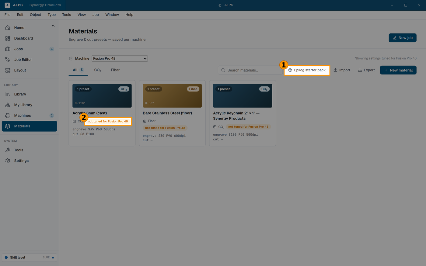
① Epilog's published starting settings, ready to import ② ALPS tells you when a preset was NOT tuned for your machine — treat it as a starting point
Materials stores settings by material and thickness so you are not retyping them.
⭐ ALPS ships Epilog's published starting settings. Treat them as the starting point they are labelled as, and save your own once you have tested them — a material entry that reflects your machine is worth more than any published table.
6.9 Fiber galvo settings ■
These appear only on a fiber galvo machine (the G100 and similar). They have no meaning on a CO2 flatbed and do not show there.
6.9.1 Fill — how the beam covers a solid area
A galvo fills a shape by sweeping lines across it. Three settings decide how.
| setting | what it does |
|---|---|
| Line spacing | distance between fill lines. Tighter = darker and slower. |
| Passes | how many times each fill is repeated. |
| Fill style | how the beam moves between lines — see below. |
Fill style has two options and the difference is real, not cosmetic:
- Sweep (the default) lifts the beam at the end of every line and starts the next one from the same side, so every line is marked in the same direction.
- S-Sweep never lifts — the beam runs down one line and straight back along the next in a continuous serpentine.
⭐ S-Sweep is faster because the beam stops less. Sweep is more even, because every line is marked travelling the same way; a serpentine marks alternate lines in opposite directions and on some metals that shows as fine banding. Start with Sweep, and try S-Sweep when speed matters more than an even tone.
⭐ Cross-hatching is the strongest evenness control on metal — filling twice at different angles (0° then 90°) covers what a single direction leaves striped.
6.9.2 Wobble ■
Wobble oscillates the beam side to side as it travels along a cut line, so a single thin line is marked as a ribbon instead of a hairline.
- Wobble size is the width of that ribbon.
- Wobble step is how far the beam travels per side-to-side cycle — smaller is a tighter weave.
Two reasons to use it:
- To thicken a line that is too fine to see, without redrawing the artwork.
- ⭐ To cut thin metal a fiber otherwise cannot. A wider path removes more material per pass and keeps the beam on the cut longer, which is often the difference between scoring the metal and going through it.
⚠ Wobble makes the line wider than you drew it, by the wobble size. On anything where the dimension matters, allow for that — it behaves like a much larger kerf.
6.9.3 Beziers ■
Controls how curves are described to the machine: on (the default) sends true curves, off sends the corner points of the flattened path. On is normally right — it is what the machine's own software sends, and it produces smoother curves. Turn it off only if you are chasing a difference against a reference file.